JFTech VMS setup and user guide, JF-Video Management Software (hereinafter referred to as VMS ) is latest developed client software for our products. The suppressible toolbar, succinct GUI and rich functionality make it very intelligent and user-friendly monitoring management software which can be used in various scenes.
JF-Video Management Software (hereinafter referred to as VMS ) is latest developed client software for our products. The suppressible toolbar, succinct GUI and rich functionality make it very intelligent and user-friendly monitoring management software which can be used in various scenes.
This software could be used for connecting kinds of devices, such as DVS, DVR and so on. This introduction only presents the operation on software, if need detail function settings please refer to product specification.
User & privacy management
VMS support three-level organization management system, user management and permissions management.
Use data interface
System data interaction use data interface, could support kinds of database flexibly, like SQL, MYSQL, XML and so on.
Support edit and add device by Excel table
Allows users to import or export devices using the binary files(filename extension:bin),much more easier in coping with the maintenance of a large batch devices. which improves system’s useability and significantly reduces the workload of maintenance.
Smart video transmission protocol
Using the Smart video transmission protocol, the system can fully utilize the bandwidth of a network. Especially in situations when the bandwidth of the front-end network condition was limited. The system can still operates under a narrow bandwidth, without reducing the quality of the images.
Perfected video surveillance system
Allows the real-time surveillance and many other abilities. Such as alarm activated video record, auto-surveillance record, record playback and etc. Able to control the recording on every channel.
Dynamic decoding buffer adjust
The real-time surveillance is able to modify the priority setting between the video’s fluency and it’s real-timing with flexibility. Should the user chose to give fluency the priority, the system will provide much fluent images. Otherwise , the system will focus on providing real-time images. Thus, the system is capable of satisfying all kinds of needs.
Centralized management
All the data of the system is under centralized management. This allows remote users to conduct real-time surveillance and video playback via internet.
Fine operability
With the control authority, users can control and configure every surveillance post via client software. Also has an E-map function integrated.
High integration level
Other kinds of relevant information such as alarm information, voice message are also integrated in the system.
High reliability
There is also a fault-tolerant mechanism designed for the system, in order to keep the data intact, and to keep the system reliable.
Fine expansibility
Service-oriented system design, provides fine ability to expand and to adapt. Which can considerably protect user’s investments.
Other features
Allows to use E-map
Allows multi-channel playback
Able to connect to multiple devices and check their video(both real-time and playback) XML data storage
Compatible with multiple protocols for rocker keyboard Multiple kinds of alarm devices are allowed, such as CK,VISTA
Compatible with multiple kinds of 3D positioning protocols. Able to perform 3D positioning within the viewing area.
JFTech VMS setup and user guide
Read More : XMEYE VMS PC CLIENT Setup Guide
CPU: P4/2.0G
Graphics CPU: ATI9800 or above(two channels) Graphics memory: 128MB or above
Graphics bus Width: 128bit
The graphics card must be able to perform hardware scaling(such as ATI and TNT2 PRO). Network interface card:100/1000M
Note: If devices have high resolutions or there are too many channels at the same time, in order to have a good performance, system requires much advanced hardware than we listed above.
This software is compatible with windows Vista/Xp/2000/2003/7/8/10(windows 98 is not recommended)
Please shut down all activated anti-virus software and firewalls during the installation process, otherwise the device may not be detected.
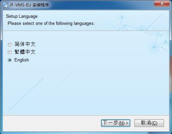
 to start the VMS setup sequence,select your language in the following dialog box.
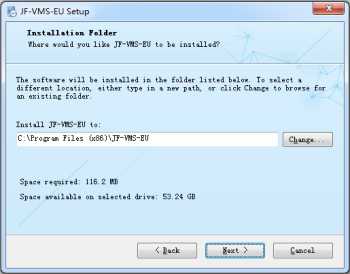
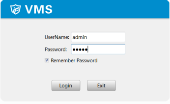
Default password: admin
 appears on your desk top.
Note: Different devices may have different functions and options in the menu)
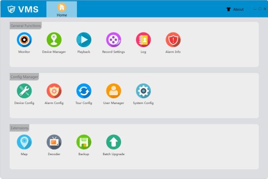
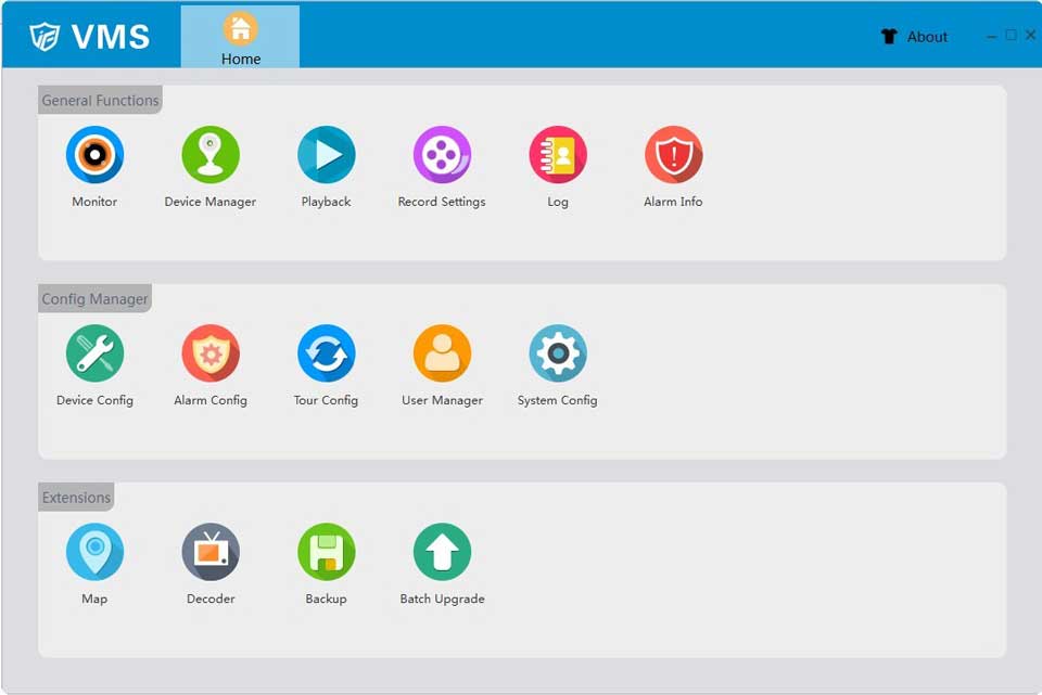
The home page of VMS is shown below.
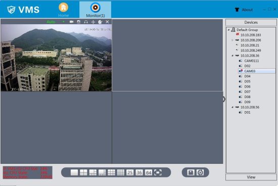
Click the “monitor” button to open the monitor page.
【Monitoring view】
|
Monitoring view |
The monitoring view provides live view of every monitoring channel |
|
Window operation menu |
The menu controls all the devices within the window |
|
Device list button |
Click “Device” to show the list of all devices |
|
View list button |
Click “View” to show the list of all views |
|
Multi-screen switch |
To change the viewing number of multi-screen monitoring, simply select the “single screen” ,“four screens” ,“six screens” |
|
Save view |
Save the current monitoring view |
|
tour |
Follow the preset tour plans to tour |
【Open the channels】
Select one of the windows in monitoring view, then double click one of the channels in Devices list
【operation menu】
Choose display scale,
auto resize turned on by default.

|
|
Temporary manual record. |
|
|
Instantaneous manual record. |
|
|
Click to enable audio. |
|
|
|
|
|
Adjust the color of video on VMS, Not of the device.
|
|
|
Disconnect the video. |


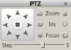

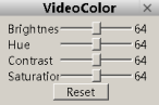

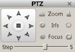
【PTZ control】
Click the button of PTZ and pop up the control interface.
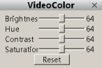
【Video color】
 Click the button of color adjustment and pop up the interface for adjusting video color.
Click the button of Device Manager, then enter the page of device manage, as it is shown below:
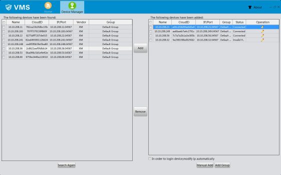
【Search again】Click this button, the software starts to search for online devices, the result of the search will be listed in the left block.
【Add】Select the device which have been found in left block(single click to select) and click “add” button, it could be added in the right block.
【Remove】Select the device in the right block and click “remove” button, this device could be removed.
【Manual Add】We could add device by input device’s IP、port、username and password manually.
【Add Group】Add new group which could place different kinds of devices inside, makes it simple to manage.
【Edit】Click the “Edit” button to modify added device’s information.
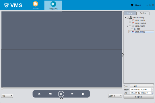
Click the Playback button and enter the playback page, as it is shown below:
|
Video playback interface |
This interface is used to show playback videos |
|
Playback operate menu |
Able to operate on record files |
|
Playback type |
Able to choose to playback in chronological order or in file type order |
|
Multi-screen switch |
To change the viewing number of multi-screen playback, simply select the “single screen” ,“four screens” ,“nine screens” |
|
Local /device list |
Set to search local or device for record files |
|
Search list |
List the record files that has been found |
|
Search time window |
Set the time window that you want to search for record |
【Playback operate menu】
|
|
Open file |
|
|
Fast play |
|
|
Play |
|
|
Slow play |
|
|
Stop |


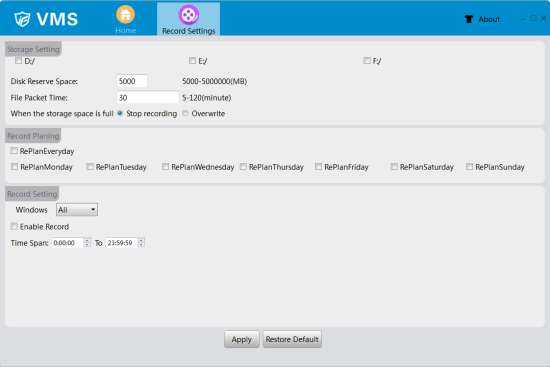
Click “Record Settings” to enter it’s page, As shown in Figure below
【Storage settings】
Storage settings allows users to set a disk letter in order to store record files into the corresponding disk ;
The disk reverse space is specially set aside not to store video;
User can set the file packet time , in order to pack the files at corresponding time;
when the storage reached it’s full capacity, users can choose to stop recording or overwrite old files.
【Record Planning】 Set record planning
【Record settings】
Select corresponding window, set user’s time span and tick Enable Record, click apply to save the setting. Thusly the VMS will start recording appointed window once reach the selected time span.
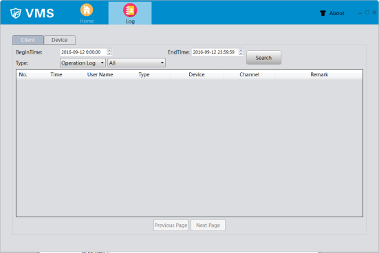
Click “Log” button to enter the log page, as the picture shown below.
【client end】
Click the “client” button, set designated time span(type in begin time and end time)and start searching, the system can find client’s logs during the chosen time span. And also can search by log types.
【device end】
Click the “device” button, set designated time span(type in begin time and end time)and start searching, the system can find device’s logs during the chosen time span. And also can search by log types.
【previous/next page】
Click to turn the log page.
Click Alarm Info to enter the Alarm Info page, as the picture shown below.
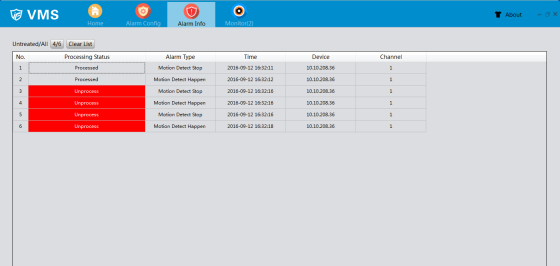
【alarm information list】
In the list all the unprocess and processed alarms are shown, double click the unprocess information will change it’s status into processed. Click “Clear list” will clear all alarm information.
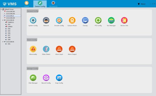
Click “Device Config” to enter Device Config page, as the picture shown below.(display differences might exist when it comes to different devices).
Click “System Config” to enter System Config page , as the picture shown below.
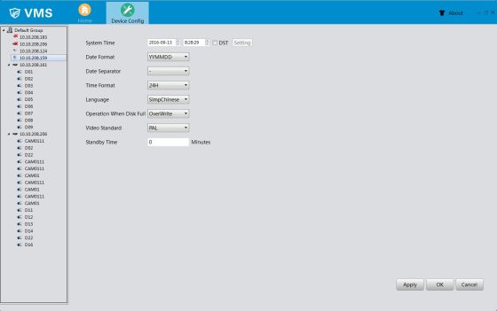
【System time】to set time for recorder
【DST】tick DST, click setting to set the beginning and the end of summer time=
【Date format】set the display format of date
【Time format】set the display format of time
【Language】 28 kinds of languages such as Simplified Chinese, traditional Chinese, English, Persian, Finnish, French, Greek, Hungarian, Italian, Japanese, German, polish, Portuguese, Russian, Spanish, Thai, Turkish, Vietnamese, Romanian language, language of Brazil, Indonesian, Swedish and Arabic, Bulgarian, Czech, Hebrew
【Operation when disk full】when the storage reached it’s full capacity, users can choose to stop recording or overwrite oldest files.
【Video standard】there are two kinds of video standard, PAL and NTSC. the standard in the recorder should be in correspondence with it’s front end cameras
【Standby time】able to set standby time from 0 to 60 minutes
TCP/IP setting
Click “Network settings” to enter network setting page, select “TCP/IP” to config, as the picture shown below.
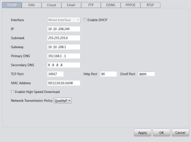
【Interface】To show the type of network interface the device is using
【IP】To config the IP address of the device
【Submask】To config the subnet mask of the device
【Gateway】To config the gateway of the device
【Primary DNS】To config the primary DNS of the device
【TCP Port】To config the TCP of the device
【Http port】To config the Http of the device
【Onvif port】To config the Onvif of the device
【MAC address】To config the MAC address of the device
【Enable high speed download】Tick this option to speed up the download process
【Network transmission policy】Able to choose adaptive/quality Pre/fluency Pre/transmission Pre
DAS setting
Click “DAS” to enter DAS page, as the picture shown below.
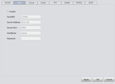
【Enable】 tick to activate DAS
【SerialNO】config serial number of the device
【Sever address】config the sever address for the device
【Sever port】config sever port for the device
【Username】config user’s name
【Password】config user’s password
Cloud setting
Click “cloud” to enter cloud page , as the picture shown below.
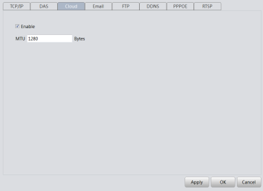
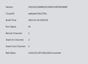
【Enable】 tick to activate the cloud service, users are able to remotely login using the exclusive serial number of the recorder via http://cloud.jufenginfo.com/index?request_locale=en, to view and to manage the recorder. The serial number can be found in Home/Device Config/Version Info
【MTU】config Maximum Transmission Unit figure
E-mail setting
Click “E-mail” to enter E-mail page , as the picture shown below.
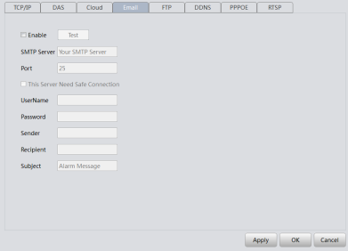
With necessary parameter settings, the device will send alarm information and snapshot picture to appointed mailbox.;Please enable the snapshot function in the alarm setting before use, otherwise there will be no photo.
【SMTP sever】the SMTP sever address, could be an IP address or a domain name (the DNS should be set correctly in order to use domain name )
【Port】sever port number
【SSL】choose to use secure socket layer or not
【Username/Password】sender’s username and password
【Sender】exact address of sander’s mailbox
【Recipient】exact address of alarm recipient’s mailbox. three recipient’s addresses at most, use a semicolon to separate.
【Subject】the subject of the alarm E-mail, users can config according to their own needs
FTP setting
Click “FTP” to enter FTP page , as the picture shown below.
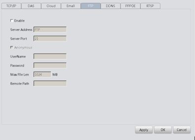
【Sever Address】appointed FTP sever’s address, if the sever is in wide area network, the recorder must be connected to the wide area network , too
【Sever port】FTP sever’s port number FTP (default number 21)
【Username/password】the username and password that user registered on the FTP sever, which also requires it’s authority.
【Anonymous】tick the anonymous allows users to upload files to the FTP sever without logging in, in order to make this work, please make sure the FTP sever allows anonymously access.
【MAX file len】the max file volume of each file packet, default value 128M
【Remote path】the file path in the sever that is meant to receive uploaded data Note: this account have upload authority to the sever.
DDNS setting
Click “DDNS” to enter DDNS page , as the picture shown below.
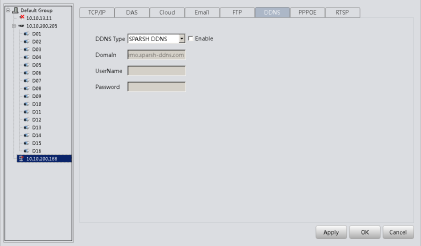
【DDNS type】to choose the DDNS service provider
【Domain】the domain name binding with the record’s IP , usually provided by DDNS service provider
【Username/Password】the username and password registered in DNS service provider Note:the DNS setting should be configured correctly
PPPOE setting
Through the PPPOE, The recorder can be remotely accessed through Wide Area Network. This requires an exclusive dial-up networking
Click “PPPOE” to enter PPPOE page , as the picture shown below.
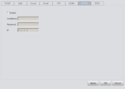
【Enable】tick “enable” to activate PPPOE
【Username/Password】type in username and password provided by ISP, save and restart recorder according to the tips. The recorder will establish Internet connection after restart, the IP address will be shown in the IP column
RTSP setting
View recorders’ videos using non IE kernel browsers and streaming media.
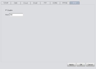
【Port】the default port number for devices is 554
Click “Encode Config” to enter Encode Config page , as the picture shown below.
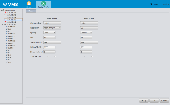
【Compression】standard H.264;
【Resolution】able to select display resolution , multiple choices such as 1080P ,720P, 960H…
【FPS】able to select FPS frame rate, when under PAL standard, the frame rate is adjustable from 1 to 25, when under NTSC standard, the frame rate is adjustable from 1 to 30
Note: low frame rate will have an impact on the fluency but occupies smaller flow
【Stream control】two strategies for stream control VBR and CBR. When user sets VBR, there are six grades of quality choices. When the system is under CBR setting, users can manually sets the bit rate to suit the network condition.
【Quality】when VBR was chosen in the stream control. Users are able to choose the quality of the videos. High quality videos also requires a large bit rate. the bit rate changes in different situations, dynamic scenes need larger bit rate than steady scenes, the scenes’ high complexity also contributes to a larger bit rate.
【Bitrate】when CBR was chosen in the stream control , users are able to control the bit rate by setting the ideal bit rate number. Once set, the bit rate will not rise or fall dramatically with the changes of scene, it fluctuates around preset number.
【I frame interval】interval time between key frames, optional from 2 to 12, smaller this figure was set the larger bit rate there will be, hence the better video quality
【Video/Audio】tick the “audio” to enable audio function, then user are allowed to click the audio sign in the monitoring view to conduct audio surveillance .only when extra stream was enabled can users view video through extra stream
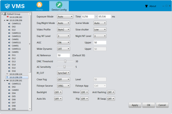 Click “Camera Param” to enter Camera Param page , as the picture shown below. Users are able to modify IPC parameters
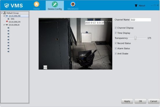
Click “Overlay” to enter Overlay page, as the picture shown below.
【Channel Name】able to change channel names(21 Chinese symbols or 42 English letters maximal)
【Time Display】tick to display time and date on surveillance view
【Channel Display】tick to display channel number on surveillance view
【Record status】tick to display record status on surveillance view
【Alarm status】tick to display alarm status on surveillance view
【Transparency】adjust transparency of the back ground from 128 to 255
【Region mask overlay 】tick to select region mask overlay, click “setting” to enter the corresponding channel. user can select an area to cover up by using the mouse. The covered area are black blocks .
Click “PTZ Config” to enter PTZ Config page, as the picture shown below.
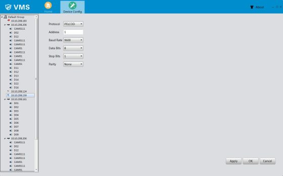
【Channel】users can choose the channel they would like to config in the menu
【Protocol】select the chosen PTZ protocol
【Address】chosen PTZ address, default figure is 1
【Baud rate】choose PTZ baud rate, default figure is 115200
【Data bits】including 5 to 8 options, default figure is 8
【Stop bits】including two options, 1 and 2,default figure is 1
【Parity】4 kinds of check methods: odd parity check , even parity check , mark check and space check , default method is none
Click “Tool Manager” to enter Tool Manager page, as the picture shown below.
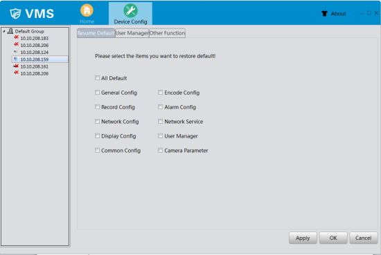
Restore default configuration (able to set default selectively)
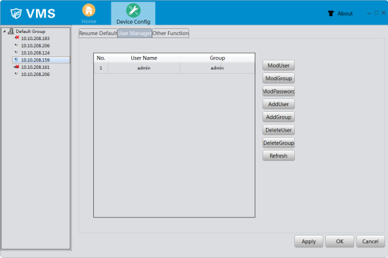
Click “User Manager” to enter User Manager page , as the picture shown below.
To manage users’ authorities
note: 1.The length of all username cannot be more than 8 bytes, spaces can only be among the string , not at the beginning or the end of the string. only legitimate characters:
Letters, numbers, underline, minus, point .
【ModUser】modify existed user account
【ModGroup】modify existed user group account
【ModPassword】modify existed user’s password, the length of all password cannot be more than 6 characters, spaces can only be among the string , not at the beginning or the end of the string.
【AddUser】add user account to group and modify user’s authority. Enter the menu type in username and password, than choose group. also have to choose to allow account multiplexing or not
【AddGroup】add a new user group and modify user group’s authority. There are 33 authorities are provided, including shut down device, real-time surveillance, playback, record setting , back up…
【DeleteUser】delete chosen user ,first choose the user than click “delete”
【DeleteGroup】delete chosen user group, first choose the user group than click “delete”
【Refresh】Refresh device list
Click “Other Function” to enter Other Function page , as the picture shown below.
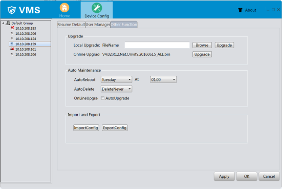
【Upgrade】Select upgrade file to upgrade the device or upgrade online
【Auto Maintenance】Config auto reboot time and auto delete type; Activate auto upgrade or not
【Import and Export】Import or export config file.
Click “Version Info” to enter Version Info page, as the picture shown below.
Click “Abnormality” to enter Abnormality page , as the picture shown below.
To supervise the storage of the recorders and network condition. Alarm when any abnormality occurs.
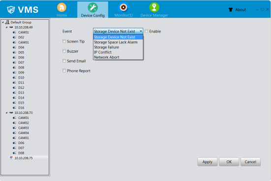
【event】five different settings for each kind of event
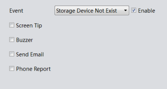
【Storage Device Not Exist】:the recorder can not detect storage device(Could be a damaged link to the storage device or storage device damage),will trigger alarm according to preselected alarm mode.
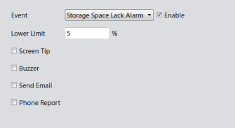
【Storage space lack alarm】:allows users to set a minimum threshold for Storage space, once breached, will trigger alarm according to preselected alarm mode.
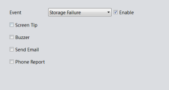
【Storage Failure】: It would happen alarm once device detect the storage device is damaged.
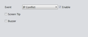
【IP Conflict】:recorder find a device using same IP address as it’s own, and triggers the alarm
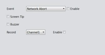
【Network Abort】: It would trigger alarm and record the video if these functions are enabled when the device lose network connection.
Click the button of Video Detect, it would appear the interface accordingly, as shown below:
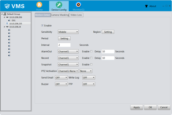
【Enable】Tick the check box √ in front of enable means that the motion detect function is on. Then you can set up the corresponding settings.
【Sensitivity】Choose in the six options according to the sensitivity, Lowest, Lower, Middle, High, Higher and Highest.
Note: Only the motion detect under hybrid mode/ full analog mode have this function of setting sensitivity, and also only the analog channel can set region.
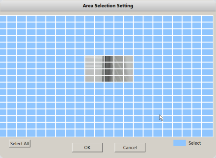
【Region】Click [setting] to enter the set area. The area is divided into PAL22X18. Black block means the motion detect defensive area. Blue block means the unfenced area. You can set the area as followed, Drag the mouse and draw the area. Default: all selected blocks are detection area.
Note: Only the motion detect under hybrid mode/full analog mode have this function of setting region, and also only the analog channel can set region.
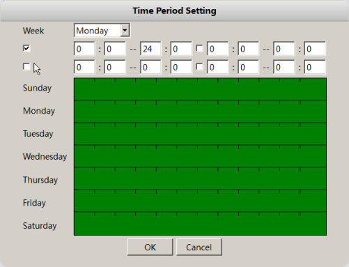
【Period】Trigger the motion detect signal in the set time section. You can set according to week or set uniformly. Each day is divided into four time sections.
【Alarm Out】Start the external equipment of corresponding linkage alarm when the motion detect is turned on.
【Delay】Delay a few moments and stop when the alarm state is turned off. The range is 10~300 seconds.
【Record】Choose the recording channel (multiple option supportive). Trigger the video signal when the motion detect is turned on.
Note: Set in the [recording setup] and perform the linkage recording. Start detecting video files in the corresponding time section.
【Snapshot】Choose the recording channel (multiple option supportive). Trigger the snapshot when the motion detect is turned on.
【PTZ Activation】Set the PTZ activation when the motion detect is turned on.
*Hybrid mode, PTZ link to the related PTZ information of analog channel, While digital channel model, the PTZ is link to the related PTZ information on the remote device connected.
【Send Email】Turn on it means sending an email to user when the alarm is turned on. Note: Set in the [Network] and Email.
【Write Log】Turn on it means sending a log when the alarm is turned on, you can search the log from device log.
【Buzzer】When alarm happens, device will come out with buzz
【FTP】Turn on it, the video & picture of related record channel & snapshot channel will be uploaded to assigned position.
Note:FTP upload need be set at [Network]
Select the button of Camera Masking, then could enter the interface accordingly, as shown below:
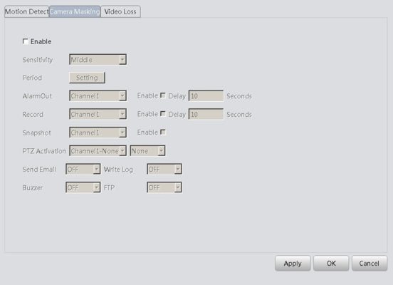
Set method: refer to Motion Detect.
Select the button of Video loss, then could enter the interface accordingly, as shown below:
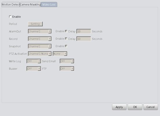
Set method: refer to Motion Detect.
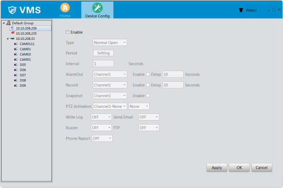
Click the button of Alarm Input, then could enter the interface accordingly, as shown below:
Alarm Input interface of IPC
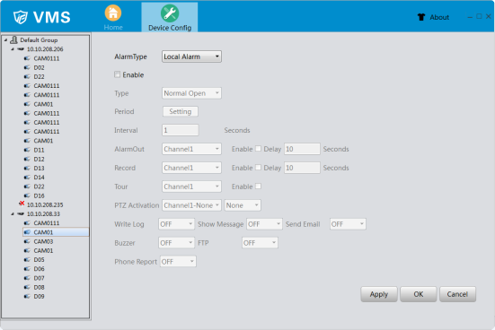
Alarm Input interface of DVR
【Type】External alarm equipment output based on switch information, which means that alarm
status should be same as device alarm type. If the equipment alarm type is normally open, it should be same as the device alarm type, and vice versa. It would pop up error alarm if the type is not same.
Other settings method: refer to Motion Detect.
Click the button of Alarm Output, it would appear the interface, as shown below:
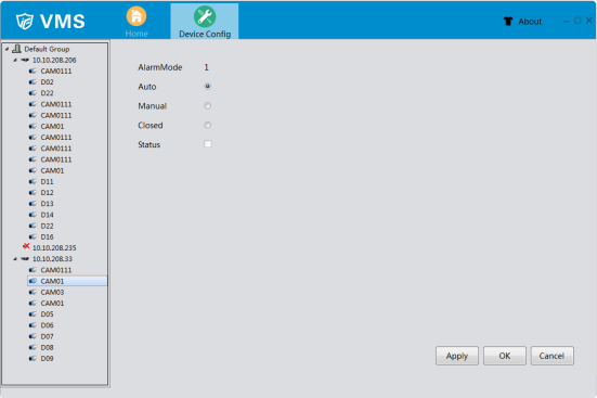
【Auto】Click the button ,the alarm output will according to the configuration.
【Manual】Click the button and the corresponding channel is always has alarm output no matter the channel in any state.
【Closed】Click the button and the corresponding channel is never has alarm output no matter the channel in any state.
【Status】Select means has alarm output at present, otherwise means no.
Click the button of Disk Manager and enter the interface accordingly, as shown belown: This function is used for manage the hard disk which is installed.
And note that if this device have the ability of snapshot, here would have one snapshot disk for store
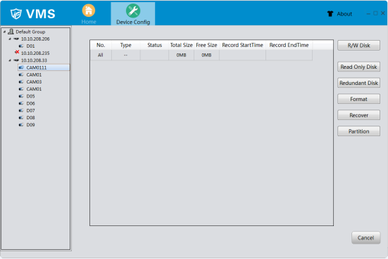
【R/W Disk】after set, this disk or partition could write or read data.
【Snapshot Disk】this disk or partition is used for store pictures which come from the function of snapshot.
【Read Only Disk】this disk or partition could only be read, can’t written in new records or pictures.
【Redundant Disk】this disk or partition is used for double backup the video files.
【Format】select one disk or partition, click this button could format accordingly.
【Recover】select one disk or partition, click this button could repair the disk or partition which is error.
【Partition】able to partition the disk which is selected manually
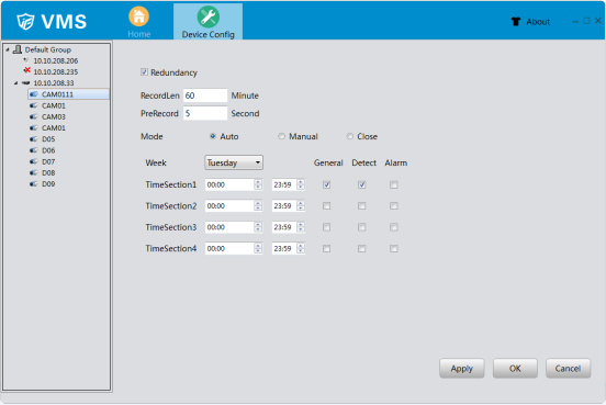
Click the button of Record Config, then could enter the interface accordingly, as shown below:
【Redundancy】choose the redundancy function option to implement the file double backup function. Double backup is writing the video files in two hard disks. When you do the double backup, make sure that there are two hard disks installed. One is read-write disk and the other is redundant disk.
【RecordLen】Set the time length of each video file. 60 minutes is default value.
【PreRecord】Record 1-30 seconds before the action.(time length is decided by the code stream)
【Mode】Three record mode: Auto, Manual and Close
Auto: Record according to the set video type(common, detection and alarm) and time
section.
Manual: Click the button and the according channel is recording no matter the
channel in any state
Close: Click the stop button and the according channel stops recording no matter the channel in any state.
【Period】 set the time section of common recording, the recording will start only in the set range.
【Record type】Set recording type: General, Detect and Alarm.
Click the button of Snap Config, then could enter the interface accordingly, as shown below:
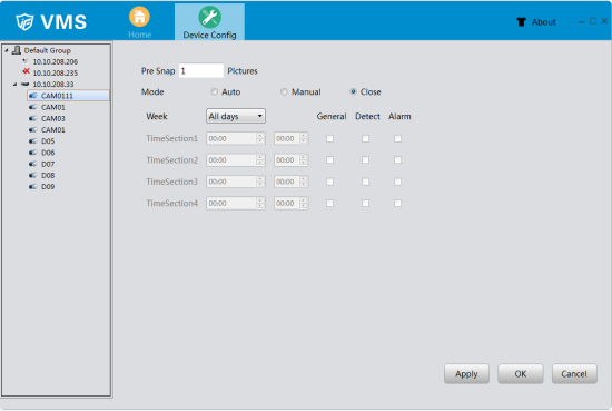
【Pre Snap】once happen alarm, it would snapshots 1-5 pictures before alarm triggered to snapshot, by default it is 2 pictures.
Other settings please refer to Record Config
Click the button of Alarm Config, then could enter the interface accordingly, as shown below:
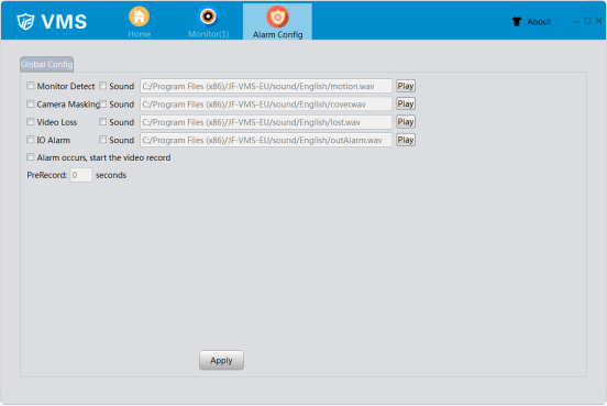
【Alarm type】there are four types of alarm: Monitor Detect, Camera Masking, Video Loss and IO Alarm.
【Sound】VMS could cause alarm sounds according once alarm triggered. Note that you should tick alarm type and the check box of sound √, as well as set up the alarm settings in device config, only this way VMS could cause alarm sounds.
【Browse】click the button of  , you could select the alarm sound file by yourself.
【Play】click this button, you could play the current alarm sound file.
【Record】Alarm occurs,start the video record;Modify PreRecord time.
Click the button of Tour Config, then could enter the interface accordingly, as shown below:
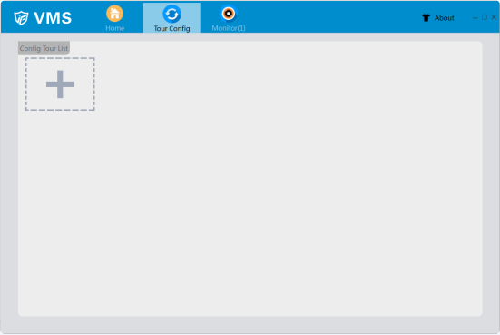
 Click the button of , you could add tour project.
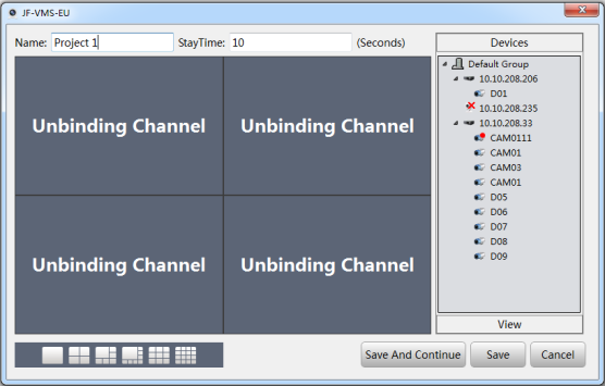
Select one of the window and double click the device channel from Device list, the channel would be added to this window, also you could add the view directly from the View list.
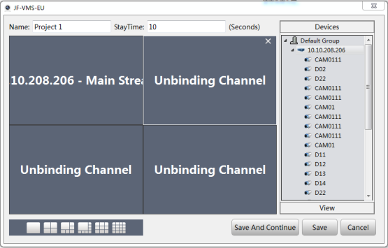
Rename the project and stay time, then click the button of Save. Or you could click the button of Save And Continue, in this way, you could continue add new project.
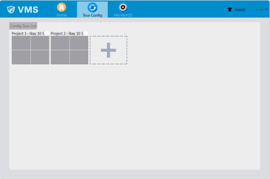
After these, you could see the interface as below show:
 Finally, you could use this function in the interface of Monitor, it would monitor according to the tour project.
Click the button of User Manager, then enter the interface, as shown below:
Note that by default there are only one managed account(account: admin password: admin)
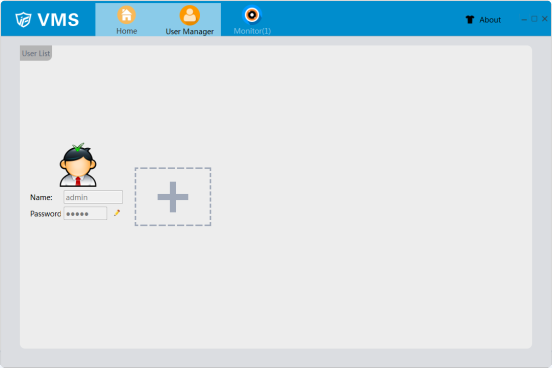
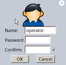
Click the button of  then could add new operator account, as shown below:
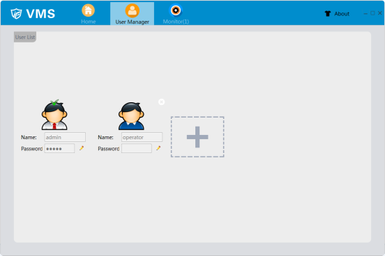
 Click the button of , then could set the password of user account accordingly, and click the button of OK to confirm.
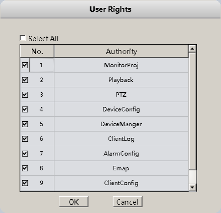
You could set the rights of user account just click the portrait itself, then it would pop up the interface as below shown.
 Click the button of , it’s to delete this user account.
Click the button of System Config, then could enter the interface accordingly, as shown below.
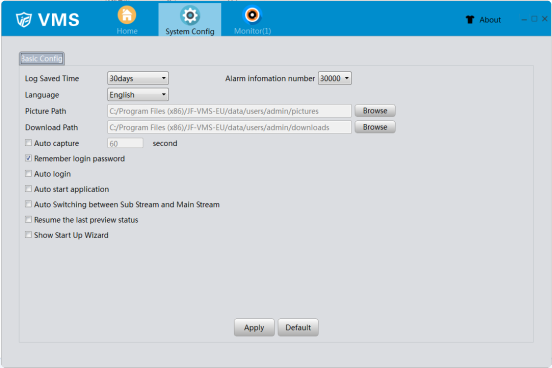
【Log Saved Time】it’s to set log saved time. The max saved time is 90 days.
【Alarm information number】Set maximum alarm information
【Language】here you could set the language of VMS, VMS should reboot after modified.
【Picture Path】this path is used for save the picture which is snapshot in monitor and you could set it by yourself.
【Download Path】this path is to save the records which you download in Playback and you could set it by yourself.
【Remember login password】Once this box is ticked, the password would be remember.
【Auto login】Once this box is ticked, VMS would auto login after start software. Note that this function need tick the box of remember login password at the same time.
【Auto start application】Once this box is ticked, computer would auto open VMS after startup.
【Auto Switching between Sub Stream and Main Stream】tick it √ in the check box then by default the live view would auto use main stream when less than 4 windows and the live view would auto use sub stream when more than 9 windows. If you use 6 windows or 8 windows, the maximum windows use main-stream and other windows use sub-stream.
【Resume the last preview status】tick it √ in the check box then VMS would auto connect the channels which are connected last time.
【Show Start Up Wizard】Once this box is ticked, it would show start up wizard
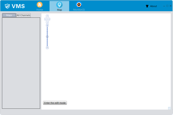
Click the button of Map, then could enter the interface accordingly, as shown below:
【Maps/All Channels】display maps which have been added and device list.
【Edit】It could be used to edit the map.
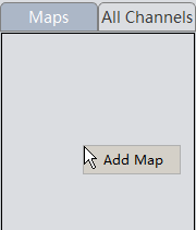
Right-Click in the Map list, then you could add map, as below shows:
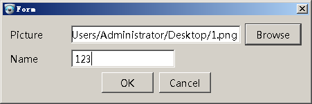
Select the map picture and input the name.
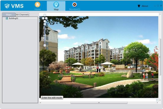 Click the button of OK to confirm, now the map have been added.
Right-Click in the view of map, it would pop up the window to add sub-map:
Select the map picture and input the name, then click the button of OK to confirm it.
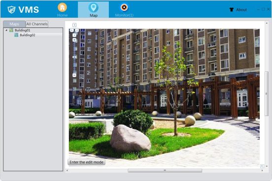
In maps list, the sub-map would appear in the original map drop list, also you could find the mark in the right display area.
Double click the mark of sub-map in display area or click it in maps list, the sub-map could open and display.
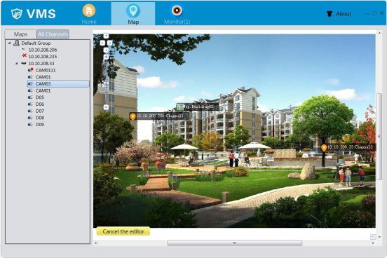
Select the channels in the list of All Channels, it could drag into map, then like below shows:
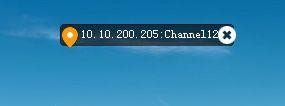
Click the button of Edit, then you could delete the device in the display area, don’t forget to click the button of OK to confirm it.
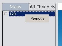
Right-Click the map which is in the Maps list, you could remove it.
It provides function to decode/preview streams by external decoder.
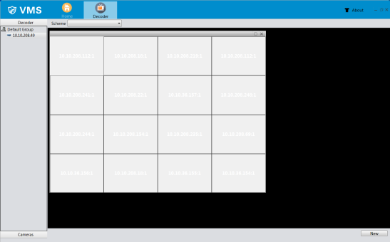 Click”Decoder”to show existed decoder device list, right click corresponding decoder would show “preview”, and click it, activate preview windows. Select specific camera, drag it into preview windows to decode video stream.
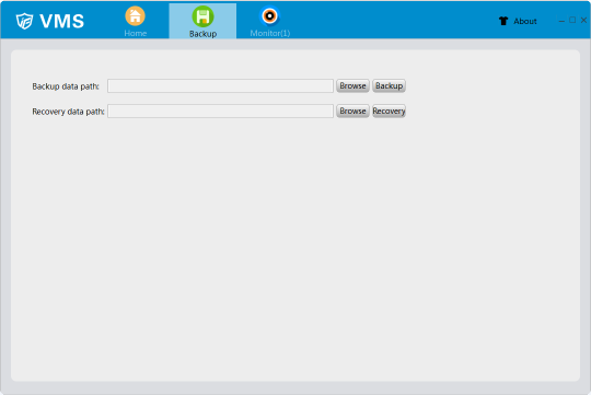
The function of Backup is used for import and export device list, which means you could export the file of devices list, as well as import it. This would be convenient for use.
Note: After import, please reboot VMS.
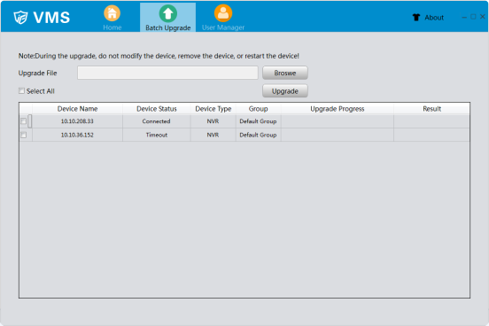
It is used for multiple devices (the same mode) upgrade together.
