Elevate CMS Full User Manual, This User Manual is for Elevate CMS software, it is used as a guide.The photos, graphics, charts and illustrations provided in this user manual are only used to explain and illustrate the purpose, they may be different from the specific product, please refer to the actual object.
Thank you for using our Elevate CMS, if you have any problems or doubts when using the products and software, please contact us anytime.
About this user manual
This User Manual is for Elevate CMS software, it is used as a guide.The photos, graphics, charts and illustrations provided in this user manual are only used to explain and illustrate the purpose, they may be different from the specific product, please refer to the actual object.
Elevate CMS Full User Manual
Read Next :
In this User Manual it is possible that we have some incorrect, or some features and operations that are not compatible with the software, or other printing mistakes. We will update the content of this User Manual according to the features upgrading or verifying, and we will improve and upgrade the description of the products. The new content may not be notified in this User Manual.
Elevate CMS is a lite platform software programmed by Invid Technology which enable user to manage the surveillance devices. It supports all Invid Elevate Series UVR, NVR, IPC and other products; offers versatile functions including device management, live preview, remote playback, remote configuration, record plan, E-Map, etc.
OS: Windows XP/7/8/8.1/10 or MAC OS
CPU: Intel Pentium IV 3.0 GHz or higher
RAM: 1GB or higher
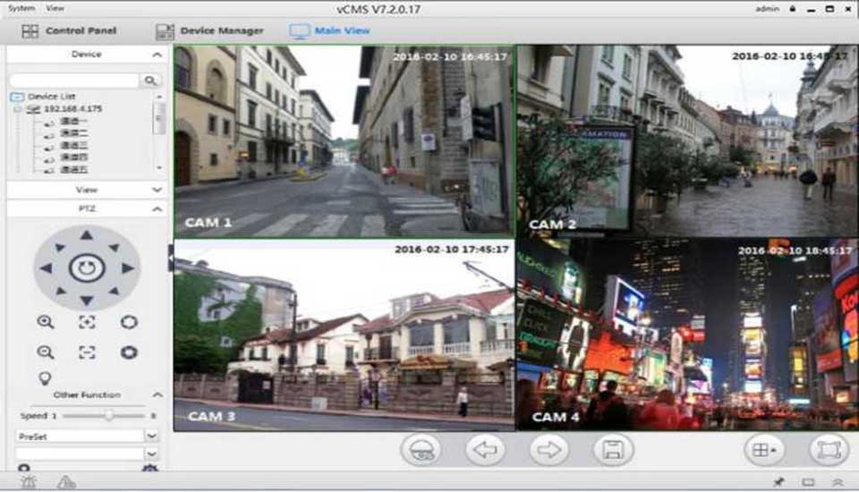
The operation interface of CMS is shown as below:
Details of menubar you can find in the table below:
| System | Lock | Lock software. No function can be done. |
| Switch user | Fill in username and password to switch user. | |
| Export config | Export config file to USB flash. | |
| Import config | Import config file to use the same configuration. | |
| View | AUX monitor | Auxiliary output. Max 4 monitors. |
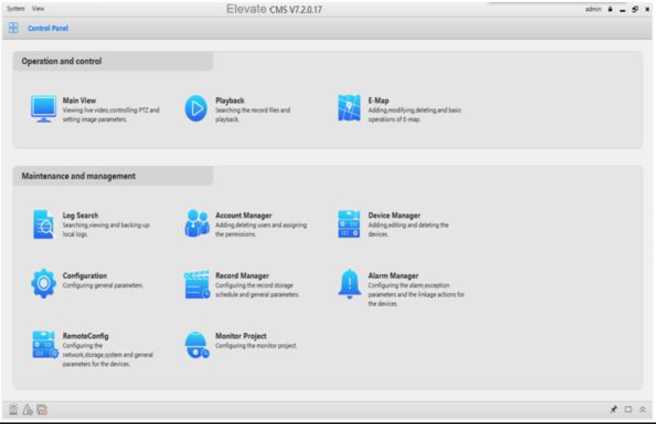
 Details of function module is as shown below:
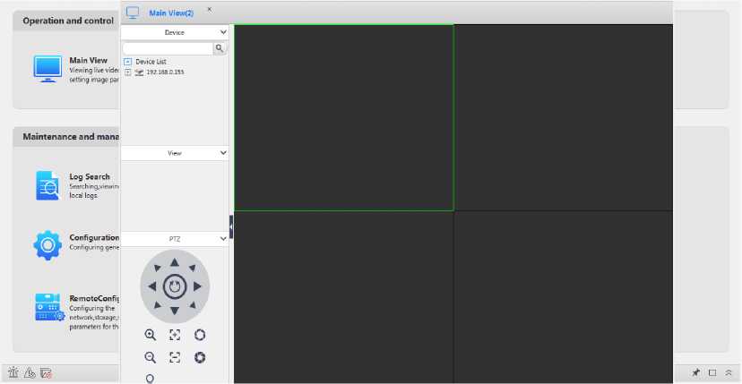
Main View: Viewing live video, controlling PTZ and setting image parameters. When you


 view the video, you can change the channel's position by click and drag the channel to another channel where you want to set.
Playback: Searching the record files and playback.
E-Map: Adding, modifying, deleting, and basic operations of E-map.
 Log Search: Searching, viewing and backing up local logs.


 Account Manager: Adding, deleting users and assigning the permissions.
Device Manager: Adding, editing and deleting the devices.
Configuration: Configuring general parameters.
Record Manager: Configuring the record storage schedule and general parameters.
Alarm Manager: Configuring the alarm, exception parameters and the linkage actions for
 the devices.
Remote Config: Configuring the network, storage, system and general parameters for the
![]() devices.
devices.
Monitor project: Configuring the monitor project.
The default path of the videos is: C:\Working Path\Elevate CMS\Record.
The default path of the pictures is C:\Working Path\Elevate CMS\Picture.
The default path of the alarm pictures is C:\Working Path\Elevate CMS\Alarm Picture.
This version of Elevate CMS is based on V1.0 and is based on device R005.
The differences between Windows and MAC system version is shown as below:
| Function Module | Function | WIN | MAC |
| Preview | Zoom (by mouse) | V(By mouse) | X |
| Image parameters setting | V | X | |
| Multicast | V | X | |
| Switch users | V | X | |
| Lock | V | X | |
| Import/export config | V | X | |
| The top right corner of the CMS interface displays the login user. | V | X | |
| Remote playback | Record download (DAV and AVI) | V | x(AVI) |
| Video encoding format display. | V | X | |
| Local record | Local timing videos can be searched. | V | X |
| Display time when playback | V | X | |
| Split screen preview | TAB pages can be dragged and dragged out. | V | X |
| E-map | Supports small window preview. | V | X |
| Device manager | Manual adding device | V | X |
| List field name sort. | V | X | |
| The device color is added. | V | X | |
| IPv6 | V | X | |
| Search by ONVIF | V | X | |
| Internet search editor (ipv4) | V | X | |
| Config | Automatic full screen at startup. | V | X |
| Record manager | General record | V | X |
| Motion detect | V | X | |
| Smart alarm | V | X | |
| External alarm | V | X | |
| Alarm manager | Linkage actions when smart alarm triggered | V | X |
| Others | Drag the mouse to adjust the CMS window. | V | X |
Here is the description of Login, Log out and switch user.

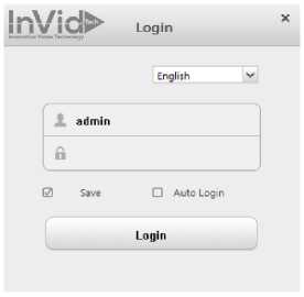
After installation, double click
. The login interface shows as Figure 2-1.
Figure 2-1 Login

![]()
User name: Default is “admin
Password: Default is 1234567u
Save: Save username and password.
Auto Login: Automatically login next time.
Language: Support English, Chinese, Czech, Italian, Farsi, Polish, Portuguese, Turkish and Russian.
After login, you can switch user on control panel, click “System” on the left of the status bar, then choose “Switch user” to get a login page. You should add one user by “Account manager” before switch user, shown as Figure 2-2.
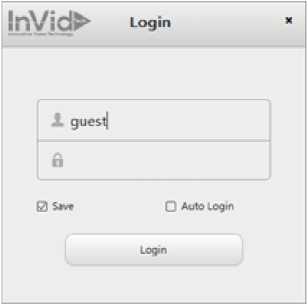
Figure 2-2 Switch user
Click button x .Input current user's password to exit CMS.
Note:
- For security, please modify your password after login.
- Donot enable save password or Auto Login in public PC.
All the functions can be found in this page, shown as Figure 2-3.
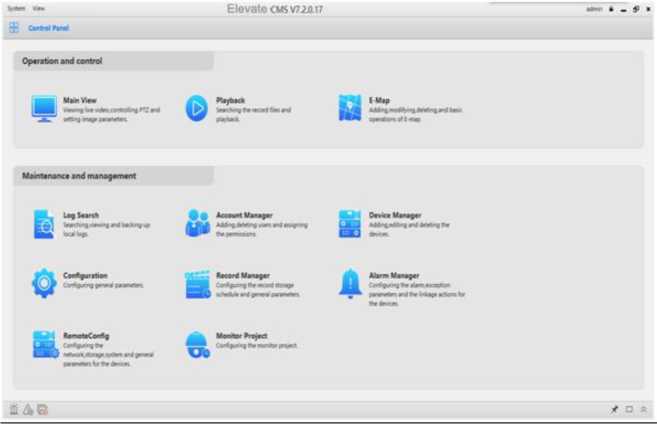
Figure 2-3 Control Panel
| Items | Description |
| Main view | Live view, Screen divisions, PTZ controlling, Local record/ snapshot, Update Channel Name, Reboot, UTC Control, Coaxial Control, Listening, Digital Zoom, Color settings, Talk, Sync time. |
| ^0^ Playback | Remote and local records/pictures search, view, playback and download. Enable cut or snapshot and record locking during playback. |
| EM E-Map | Edit/View Maps, Add/Delete spots, Edit/View alarm channel and ports. |
| Log Search | Manage local operation logs and alarm logs. |
| Account Manager | Manage groups/users, and assigned permissions. |
| ■Ml
raa Device Manager |
Search, add, modify and delete devices. |
| th . ..
Configuration |
Record/Snapshot save path, record packet time, and other settings. |
| =® Record Manager | Record schedule, record specified channels to local without Elevate CMS running. |
| Alarm Manager | Links action setting while the device triggers alarms. |
| UI
Remote Config |
View and modify settings of remote devices. |
| Monitor Project | Manage tour task and projects. |
Table 2-1 Control Panel description
![]()
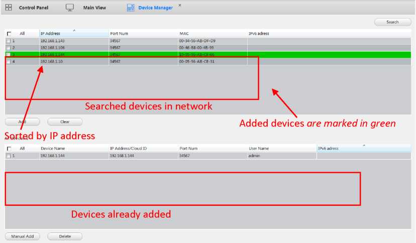
At least one device need to be added firstly before previewing.Click
button in control
panel to enter device management interface, then you can add, or modify, or delete devices,
shown as Figure 3-1.
Figure 3-1 Device Manager
There are two ways to add devices, auto search and manual add.
■ Auto: Search all the devices in your network, and then add the devices based on your need.
You can also edit the IP address by double click the IP address on the list. See as figure 3-2.
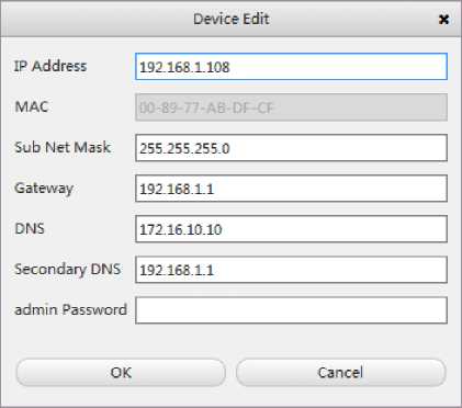
Figure 3-2 Device edit
■ Manual: Click button
.and input device information to add a device.
Shown as Figure 3-3.
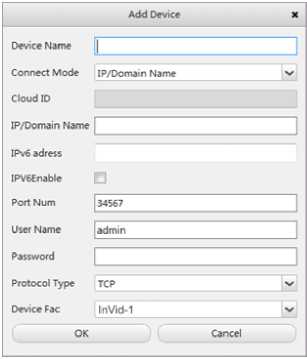
Figure 3-3 Add devices
| Items | Function Description |
| Device Name | Alias in device list. |
| Connect Mode | IP address /Domain Name or cloud ID. |
| Cloud ID | Unique identify for each device, enabled when the connect mode is Cloud ID. |
| IP address | Only enable when the connect mode is IP address. |
| IPV6 address | Enable when the connect mode is IPV6 address. |
| IPV6Enable | Used to enable IPV6 address connect mode. |
| Port Number | Default 34567, the same as device media port. |
| Username and password | Default username is admin and password is empty. |
| Protocol Type | Support TCP and Multicast |
| Device Fac | Support InVid-1 and Onvif |
Table 3-1 Device parameters
Note:
- Auto method only can add IP address type devices, if you want to add cloud ID, you must add it manually.
- Auto search can search devices in the different network.
- Searched devices can be sorted by IP Address, Port Num, Mac and IPv6 address.
- Devices that have been added are marked in green
- Manual Add support add devices by Onvif protocol.
- Manual Add support add devices by multicast.
Select the devices that you want to delete, and click the delete button to delete it. You can also delete multi devicesat once. You must close the device connection before delete the devices.
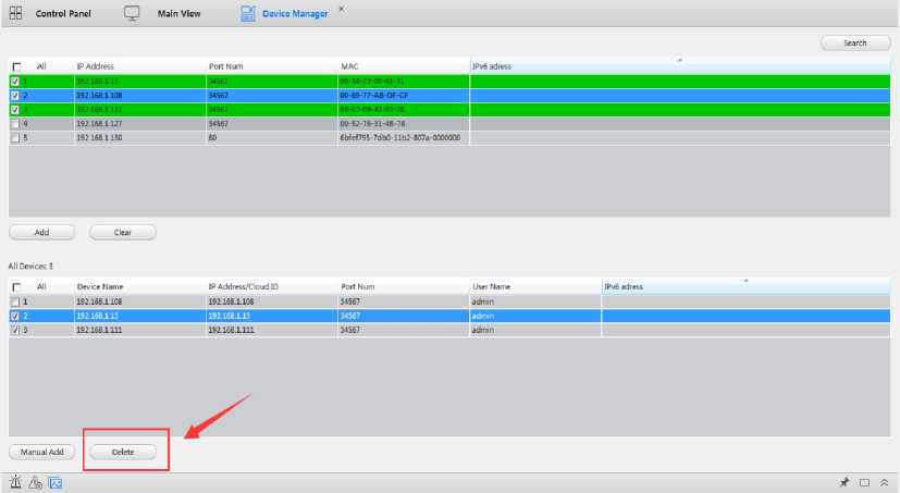
Figure 3-4Delete devices
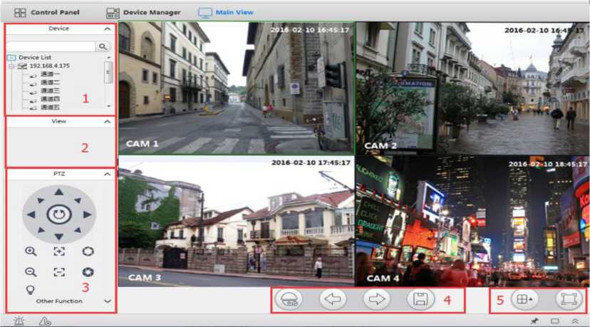
After adding the devices, click
to enter preview interface, shown as Figure 4-1.
Figure 4-1 Main View
| No. | Items | Function Description |
| 1 | Device list | Show all the devices that have added. You can connect/disconnect, choose stream, start talk, reboot device and other functions. |
| 2 | View | View list management. It can open the preview windows that saved previously. |
| 3 | PTZ | PTZ direct control, Zoom in/out, Focus +/-, Iris+/-, Preset, Auto tour and other PTZ functions. |
| 4 | Monitor Project Page up/ Page down Save view | Start/Stop monitor project and task.
Page up/ Page down when the channels cannot display in one page. |
| 5 | Windows division | Support 1/4/5/6/8/9/13/16/20/25/36/64/128 windows division, and full screen view. |
Table 4-1Preview Function description
The devices management window is shown as node tree, as shown in Figure 4-2
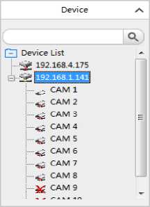
Figure 4-2
Before starting preview, you need to connect the device first. Double click on a device, shown as
![]()
![]()
means connect successfully. Double click again, shown as
means disconnect.
When the device conncet successfully, right click shows control menu as Figure 4-3
RemoteConfig
Update Channel Name
Open All Channel by Auto
Open All Mainstream
Open All SubStream Open All Mobile Stream
Close All Channels
Start Talk
Sync Time Reboot
Figure 4-3 Right menu
| Items | Function Description |
| Remote Config | View and modify the device's configuration. For details information please refer to the chapter 7.2. |
| Update channel name | When the channel name changed, use this function to update its name. |
| Open All Channel by Auto | Enable this function, when you double click a channel, it will auto select the stream depend on the current bandwidth condition. |
| Open All MainStream | Open all channels with mainstream. |
| Open All SubStream | Open all channels with substream. |
| Open All MobileStream | Open all channels with the triple stream. |
| Start Talk | Start talk with device. |
| Sync Time | Sync the device time with PC. |
| Close All Channels | Close All Channels already opened. |
| Reboot | Restart the device. |
Table 4-2 Right menu description
Note:
- Double click on a channel will enter 1 division, only view the channel selected.
- When view in multi divisions, some of the channel may notbe displayed due to the PC performance and stream encode setting.
• Streamtype will auto select according the screendiv number.
View List Management function is to save the preview split with a name, so that user can open their previously saved channels only by clicking the saved item in the list. When user want to save
(O'1
preferred view, click the icon and set the name of View, it would be saved in the View list.
AS shown in Figure 4-6.
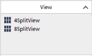
Figure 4-6
The Elevate CMS support multi PTZ function such as direction, Zoom in/out, preset and so on.
The detail functions as below.
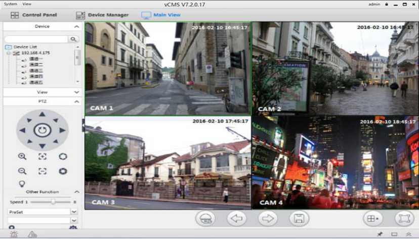
Figure 4-4 PTZ control
| Items | Function Description |
| Direction control |
|
| Zoom in/out | Press ^/^^ to Zoom in/out the image. |
| Focus +/- | Press l-+j / *. -i to change the image focus setting. |
| Iris +/- | Press *■” / w to change the image iris setting. |
| Speed | The PTZ move speed, support 1~8. |
| Lighting | Open/Close the light, need the PTZ support. |
| Preset |
description and click to save, to delete. Click —to return. … . . . . 0
place. |
| Auto Tour |
save.
|
| Auto Pan | Rotate in horizontal level. |
| Auto Scan | Press / to set left/right boarder. And press to Start/Stop Auto
Scan. |
| Pattern | Press to start/save pattern configuration. And press to Start/Stop
pattern. |
| Aux | Support custom auxiliary command. |
Table 4-4 PTZ control description
When start previewing, move the cursor to channel, it will auto show a toolbar in top of image, you can record or capture the image and other functions. Right click the mouse will open another control menu. The detail functions as Figure 4-5.
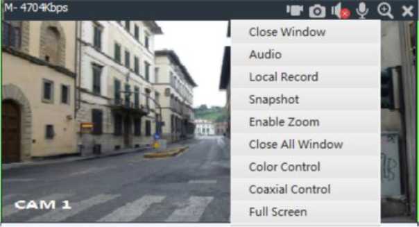
Figure 4-5 Preview right menu
| Items | Function Description |
| Q/H
Stop or start record |
Start/Stop local recording. ^Bmeans recording. The same function with “Local Record”. |
| EJIsnapshot | Capture the image, will auto open after capture. The same function with “Snapshot”. |
| ES/EQ
Mute/Unmute |
Start/Stop listening, H means listening. The same function with “Audio”. |
| E3 Intercom | Start/Stop intercom, EJmeans intercom. The same function with “intercom”. |
| 151 7
m3 Zoom |
[oJ
Digital zoom, click m3 and select area on image, the selected area will Zoom in. The same function with “Enable Zoom”. You can also achieve zoom in or out by mouse wheel. |
| ^3 Close window | Close current channel. |
| Close All Windows | Close All channels that opened. |
| Color Control | Change the image settings: Brightness, Contrast, Saturation, and Hue. |
| Coaxial Control | Control the Analog Camera via UTC function. It just appear while connect UVR. |
| Full Screen | Choose this function ,the channel video will full screen display, you can exit the full screen via right click. |
Table 4-5 Preview right menu function description
Playback as an important function in CCTV system, it can help us to check history record in anytime. The Elevate CMS has already integrated it into the customer management system, and it can support record search base on channels, device record and local record playback, download record into the local host hard-disk and others playback control operation. It's simple and easy to use.
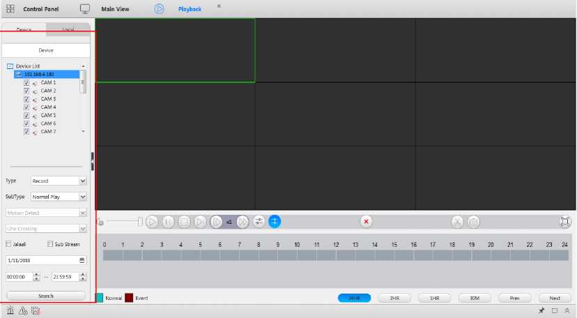
Figure5.1 Record Search
Operation Step:
- Running Elevate CMS and click the “Playback” button to open the main playback page.
- Select “Device” record which is recorded in device storage memory or “Local” record which is recorded in local host storage memory.
- Select channels which you want to playback.
- Select record type “Record” or “Picture”, subtype “Normal Play” or “Event Play”.
- Select time period which you want to playback.
- Click “Search”, then you can get search result as below.
- Double click record which you want to playback.
- You can “download” record in the search result list.
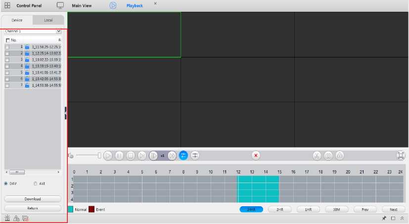
Figure 5.2 Record Search Result
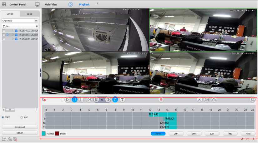
Figure 5.3 Device Record Playback
Note:
- All record channels will play when start to playback. If the channel number is less than 4, the
default playback mode is synchronous. Otherwise the default playback mode is asynchronous. Synchronous cannot support more than 4 channels.
- Elevate CMS maximum supports 9 channels playback at the same time. Playback performance is also related to the local host computer performance.
That is the playback control panel in the red circle of figure 5.3, the detail information for each button as below in the table 5-1.
Table 5-1 Playback Control Guide
| Items | Function Description |
| Play | Play the record, when it turns blue means the current channel is playing. |
| (77)
Pause |
Pause the record, when it turns blue means the current channel is pausing. |
| Stop | Stop playing. |
| [>ll
Next frame |
Play frame one by one, once click the button, the image change to pause status and move to next frame. |
| Slow playing | Play the record in slow mode, it support 1/2x, 1/4x, 1/8x speed. |
| [>l>
Fast playing |
Play the record in fast mode, it support 2x, 4x, 8xspeed. |
| △
Open file |
Open video files in local host computer, it can support video format of “.dav” & “.avi”. |
| Asynchronous | Play the records asynchronously when several channels are playing at the same time. |
| X
Synchronization |
Play the records synchronouslywhen less than 4 channels are playing at the same time. |
| X
Close All |
Close all the playing record. |
| Video Clip | Clip record and save it to local host computer. Click to start recording, click again to end. |
| [O']
Snapshot |
Snapshot the image to local host computer. |
| s
Full screen |
View all channels in full screen mode. |
| oQ>)) ‘ ■
Volume |
Change the volume sound settings. |
| Click 24HR 2HA 1HR 30M , the timeline will be adjusted to 24 hours, 2
hours, 1 hour, 30 minutes. If the channel that has record is more than 4, press next Next and previous Prev |
|
button to change pages.
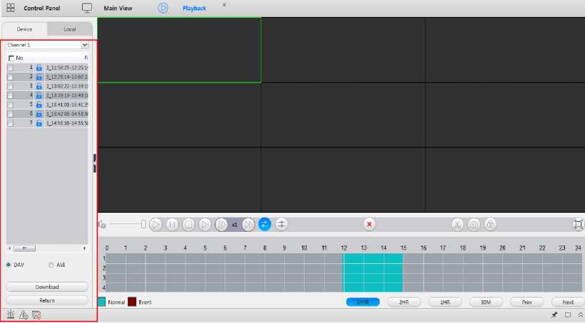
Operation Step:
- Select one or more record files in the record search page.
- Select download video format “.dav” or “.avi”.
- Click “Download” button to start download.
- You can find your download file via the path you set in the configuration page.
Note:
- The same channel cannot download and playback at the same time.
- The downloading procedure will be abort when exit file list..
Elevate CMS supply a E-Map function, that you can organize and view channel status on a map.If there is no map or enter E-Map first time, you need to add a map firstly. Click add button to add a map, input Name, Description and Path to finish add. Shown as Figure 6-1.
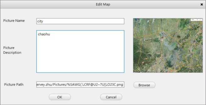
Figure 6-1 Add/Modify map
You can preview the map after added. And you can add sub map by click “Add Area” button. Drag the cam from the device list to map can add spots; You can also edit or delete the area and spot. All the cams added on the map shown in thumbnail right bottom; you can open a small window preview by clicking on the small camera icon.
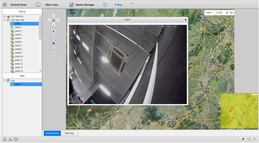
Figure 6-2 Preview map
| Items | Function Description |
| EBLE | Direction control, only available when the map is larger than the window. |
| J: | View the map in full-fill the window. |
| + — | Zoom in/out the map. |
Table 6-1 Map control
Note:
- It only supports .jpg or .bmp format pictures.
- When the alarm is triggered, the corresponding icon on the map turns to red to show alarm.
Click
icon to enter configuration interface, in this interface you can modify the file save
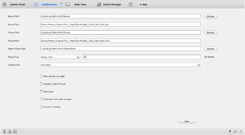
path and other configurations of Elevate CMS. Shown as Figure 7-1.
Figure 7-1 Configuration
- RecordPath: Set the path of local record and download.
- RecordRule: Save file name rules, cannot be changed.
- PicturePath: Set the path of local snapshot and download.
- PictureRule: Save file name rules, cannot be changed.
- AlarmPicPath: Set the path of auto snapshot when alarm triggered.
- PacketType: Local record time setting.
- DisplayScale:Corridor pattern setting.
- Automatic Overwrite: if this function enabled, when the storage disk is full, the record will overwrite the earliest record file, if this function disabled, the record will stop when disk is full.
- Start with the last state: The Elevate CMS will remember the current state when exit, it will recover when next time launched.
- AutoRun when PC boot: Auto launch when PC start.
- Auto Login: Auto login when Elevate CMS launched, used with “save password”.
- Dynamic Tracking: Tracking motion, need device support.
Click nV icon to enter remote configuration interface, you can modify the configurations of device, double click on device to open configuration pages. Shown as Figure 7-2.For more detail information please refer to NVR operation manual.
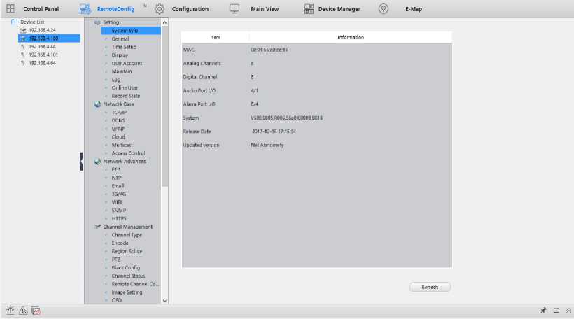
Figure 7-2 Remote configuration
![]()
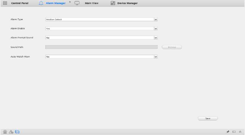
Click
to open Alarm Manager, modify the alarm setting.
Figure 8-1 Alarm link
- Alarm Type: Support Outer Alarm, Motion Detect, Video Lost, Video Shelter, Disk Full, Disk Error, Network Disconnection, Line Crossing, Area Intrusion, Region Entrance, Region Exiting, Fast moving, Unattended Object, Object Missing, Face Detection, Loitering Detection, People Gathering, Parking Detection.
- Alarm Enable: Enable/Disable alarm message.
- Alarm Prompt Sound: Play alarm sound when alarm triggered.
- Sound path: Custom sound, only support .wav files.
- Auto Watch Warning: Auto open the channels linked when alarm triggered, Shown as
Figure 8-2.
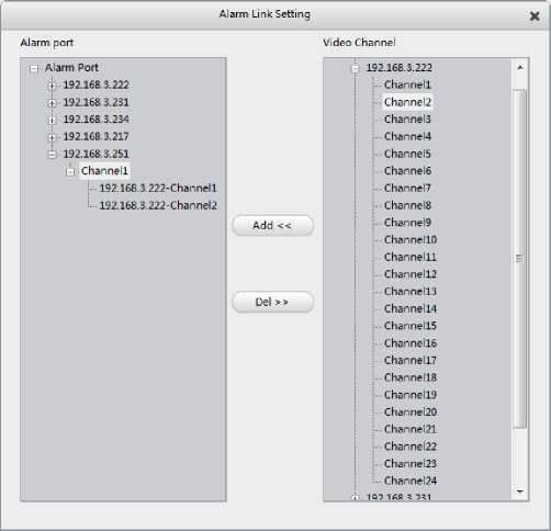
Figure 8-2 Alarm link setting
Add video channels to alarm port, when the port alarm triggered, the corresponding channels will be opened automatically. For example: Figure 8-2, it means, when channel1 of “192.168.1.10”trigger alarm, channel1 will be opened automatically like Fugure 8-3. The linked
channel can also be opened by double click the alarm log in Alarm Event.
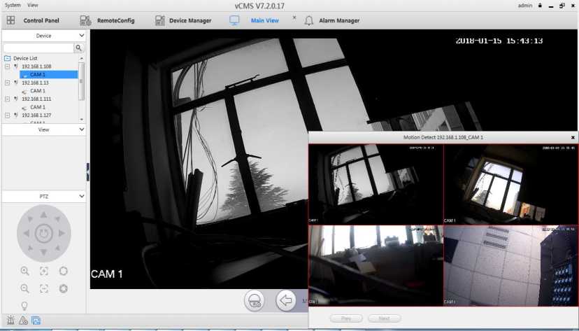
Figure 8-3 Auto Watch Warning
There always is an alarm window in the bottom of any interface; it includes device alarm and local operation information. Shown as Figure 8-1
Figure 8-4 Alarm and Event
| Items | Function Description |
| ft | Show/Hide alarm window. |
| A | Clear all the alarm or events. |
| Enable/disable alarm triggered pop-out image | |
| Auto hide alarm window. | |
| □ | Maximize alarm window. |
| ” / | Show/Hide alarm window. |
Table 8-4 Alarm and Event function

![]()
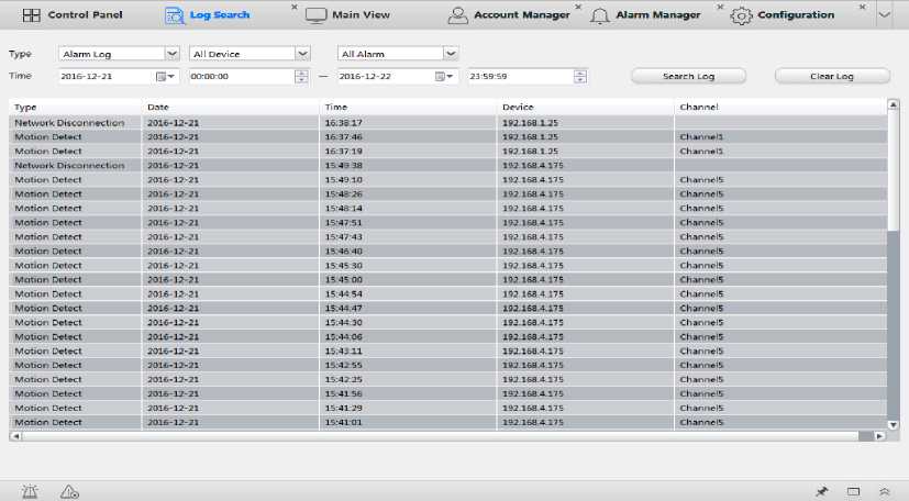
Click
to open Log Search interface, you can view all the alarm and operation logs here.
Select log type and start/end time, all the log searched shown in below. You can also clear all logs.
Figure 8-4 Operation logs
Note:
• Clear log only delete logs write in Elevate CMS, the logs in device is not deleted.
![]()
to enter user management interface, there is a default group named “administrator
and a default username named “admin”. You can add a new group by clicking add button in group.
Shown as Figure 9-1.
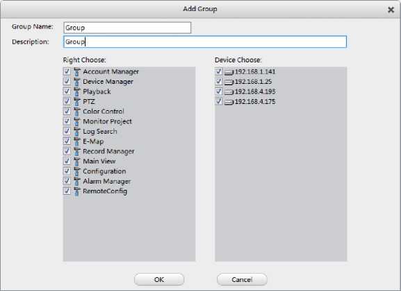
Figure 9-1 Add group
Input group name and its description, select the rights and device can be management, then click OK to create a new group. Then you can add users to this group by clicking add button in username. Input username and password to finish adding. Shown as Figure 9-2.
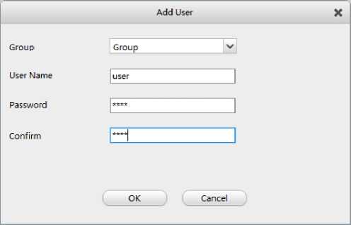
Figure 9-2 Add user
After adding, double click on the username or group can modify their settings, you can change the username's password, group, and stop/start to use it. For group you can change its rights, devices, and users.
Note:
- Default user“admin” cannot be stop, deleted or change its group.
- Default group “administrator” cannot be deleted or change its rights.
can record the camera's video by schedule without previewing. You can
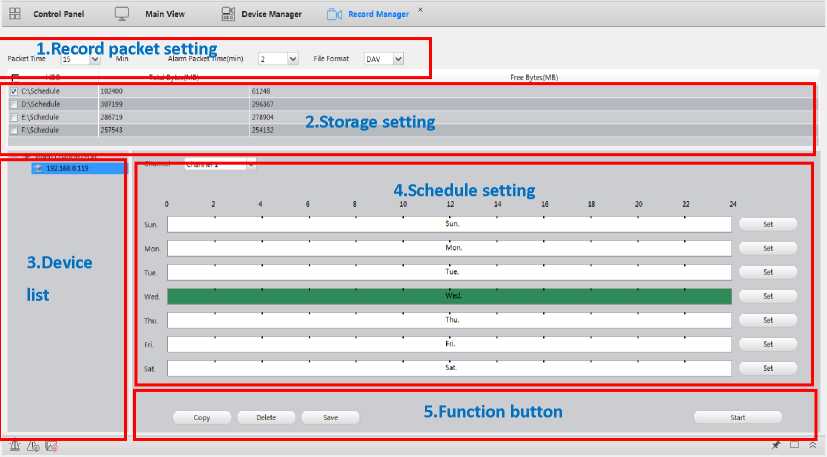
set different record schedule for every channel.
Figure 10-1 Record Manager
| No | Items | Description |
| 1 | Record packet setting | Set the normal record packet time, alarm record packet time when triggered and the record file format (DAV or AVI). |
| 2 | Storage setting | Set the record storage partition, and the default partition is X:\Schedule |
| 3 | Device list | All the devices have added. |
| 4 | Schedule setting | Set record schedule for every channel. |
| 5 | Function button | Schedule function, including copy, delete, save and start. |
Table 10-1 Record Manager
How to set schedule:
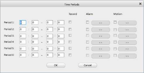
1) Click set button and set the period you want to record.
Figure 10-2 Time Periods setting
- Set alarm link channels, add channels to port, if the alarm in port is triggered, all the channels added start to record (you can add any device's channel to port). For example: Figure 10-3means, when alarm in port1 of ‘192.168.3.231' is triggered, channel1, channel2, channel3 and channel4 will be recorded automatically.
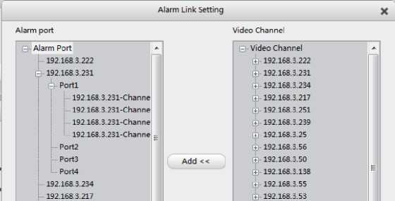
Figure 10-3 Alarm link setting
- Set motion link channels is familiar with alarm link, when Motion detected, all the channels linked start to record.
Note:
- You need to restart the schedule to take it effect.
- Some device may not support alarm in ports.
How to watch the schedule recordings:
- If the recording file format is AVI, you can find recordings in X:\Schedule, and open it by media players on PC.
- If the recording file format is DAV, you can find recordings in X:\Schedule, and open it by VPlayer.
![]()
Monitor Project, you can manage the tour task and project, press
button in main
view interface to start/stop the task.
How to create and start task:
- Click new button to create a task, input Task name, select window number (the number of windows open when tour, maximum support 36), and Main/Sub Stream. For example: Figure 10-4means, channel1 and channel2 will tour in window1.
- Change stay time for every channel.
- Click OK to finish.
- You can modify the settings after added.
- In main view interface, press button and select corresponding task to start.
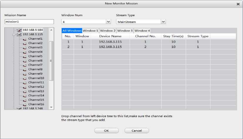
Select again to stop.
Figure 11-1 Add task
Note:
- Need to connect the device firstly before adding channels to task.
- Task name cannot be modified.
Multi task can be added to one project, the task will be affected on its start time.
How to create and start Project:
- Click new button to create a project, input name, select task and start time.
- Double click on the task can modify it.
- Click OK to finish.
4)
In main view interface, press
button and select corresponding project to start.
Select again to stop.
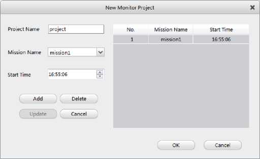
Figure 11-2 Add project
Note:
- If the start time is earlier than current time, when the project starts, the task will be activated immediately.
- Project name cannot be modified.
The Elevate CMS can separate functional modules to display independently and achieve multiple screen display.
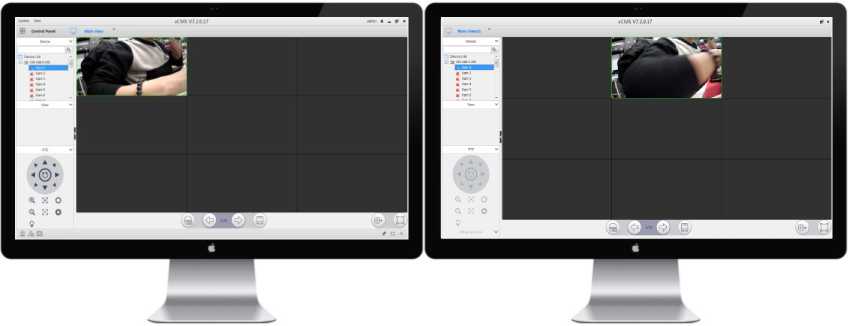
You can drag label page to the other monitor. For example, you can drag ‘E-Map' to Monitor
2, and watch preview on the Monitor 1.
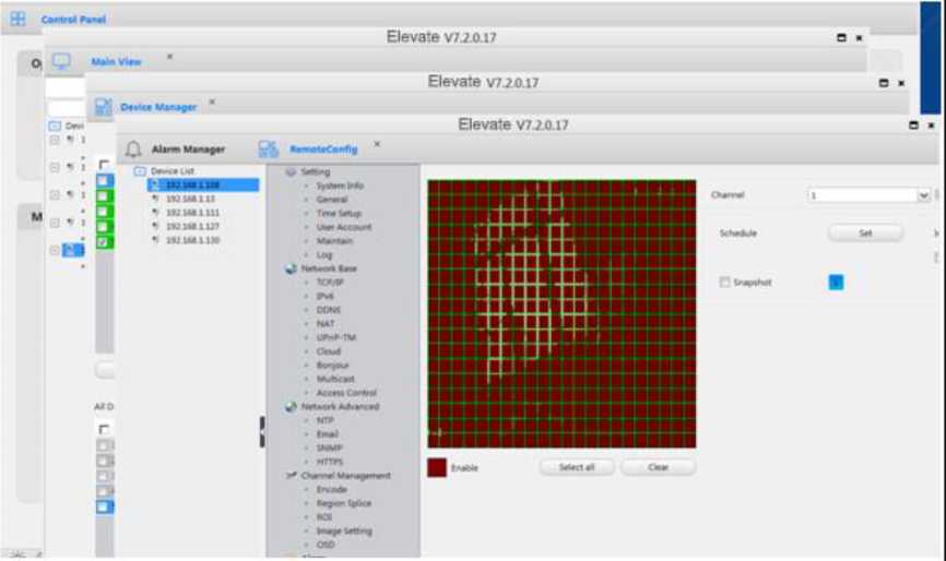
Figure 12-1 Drag Label Page
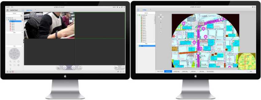
Figure 12-2 Multi-screen Display
You can click 'View – Aux monitor' to use the auxiliary monitor.
Figure 12-3 Aux monitor
After clicking it, there will be an extra window of preview (you can create three extra windows at most).And then you can drag the extra window to other monitor like the multi-screen display.
Figure 12-4 Aux Monitor
Figure 12-5 Aux Monitor
![]()
